2 What is Ovalturning |
 |
2.1 Ovalturning Definition
Ovalturning is the turning of a workpiece on a turning lathe provided with an oval chuck or on an ovalturning lathe. The turning tools were freely guided by hand. That applies generally to the turning of wood as with the normal (circular or plain) turning. When turning hard materials e.g. bone, ivory or soft stones (serpentine, alabaster, steatite) it may be necessary to clamp the turning tool in a compound slide rest. Turning tools are gouges and scrapers (profile ground) as used when woodturning. The use of routers or rotary cutters to produce a profile on an oval workpiece should not be called ovalturning but ovalmilling. When milling so called parallel curves of the ellipse are produced. They are not ellipses but regarded as ovals.
When ovalturning, using the classic oval chuck, the workpieces have an exact elliptical cross-section. Therefore the name Ellipse Turning or Elliptical Turning would be acceptable. Since the ellipse is a symmetrical oval [2.2.5], the name ovalturning is also correct, and besides, this name has been used for centuries and is more easily pronounced.
2.2 Comparison of Circular Turning and Ovalturning
Ovalturning shows, in comparison with normal turning – in the following called circular turning – essential differences. These differences are caused by the Ellipse Motion of the workpiece. This motion influences the cutting of the workpiece material, the guiding of the cutting tools, and the design of the workpiece shape.
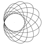
The drawing in figure 1101 shows the Ellipse Motion. The elliptical workpiece is drawn in 8 positions. It is guided to these positions by the oval chuck or the ellipse mechanism. Point C is the cutting point of the fixed tool T on the tool rest TR. While the ellipse is going through its position the ellipse midpoint runs along a circle the diameter of which equals the difference of the ellipse´s half-axes. For half a revolution of the ellipse its midpoint runs around the entire circle.
 |
 |
| Figure 1101 Ellipse Motion | Figure 1102 Central Plane |
For the explanation of other important terms look at figure 1102 in which an oval cylinder is fixed onto the faceplate of the ovalturning lathe. In this drawing the Central Plane is marked. This is an imaginary horizontal plane exactly at centre height. The Central Plane marks the Central Line on the workpiece. This line is of essential importance as the cutting part of the tool edge should always be guided exactly on this line.
Considering the cutting process: There are differences between the shaving removal on the work-cylinder and on the work-face. When circular turning, the surface of a cylindrical workpiece will form constant angles with a fixed tool edge. On an elliptical work-cylinder the angles alter periodically during the revolution. Thus, the cutting forces acting at the tool edge are also changing. The ovalturner has to take this alteration into account when guiding the tool for optimum cutting conditions to yield clean, shearing cutting and smooth surfaces. This is especially important when ovalturning wood. The materials preferred by the court turners were ivory and ebony for a “scraping” cut can produce a smooth surface because of the isomorphic structure of those materials.
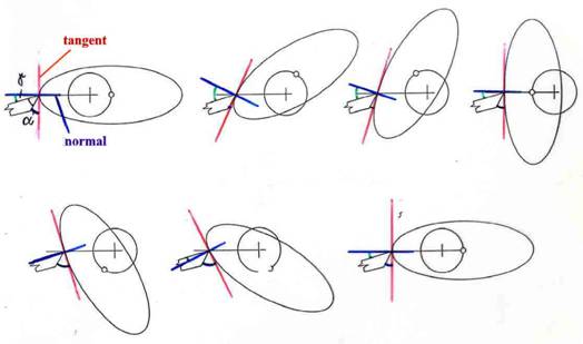
Figure 1103: Alteration of the rake angle γ and the clearance angle α
Figure 1103 shows the alteration of the angles which are important for chip formation: the clearance angle α (alpha) and the rake angle γ (gamma) when cutting the work-cylinder. At the work-face these angles remain constant. Another difference from circular turning is that the material to be cut runs with periodically altering speed over the tool edge. The cutting forces consequently also changes. The ovalturner will feel this at the tool handle.
When circular turning the work-face it does not matter along which Cutting Line the tool edge is guided to the centre because concentric circles are always generated. When ovalturning the Cutting Line is important. In figure 1104a the edge is guided along the Central Line. Cutting Line and Central Line are identical. The results are concentric coaxial ellipses or “parallel” ellipses. If the cut is not made along the Central Line, as shown in figure 1104b, concentric ellipses are produced but they are twisted to each other. All these ellipses have the same axes difference (sway). This is the parameter for adjusting the oval chuck. With circular turning the work-face has in the centre a point, with ovalturning you obtain a line.
 |
 |
Figure 1104 Cutting Line and Central Line
The art of ovalturning resides in the skill to guide the cutting area of the tool edge exactly, and unwaveringly, along the central line. Already minimal deviations have noticeable consequences on the surface. One recognizes this on the surface of facing grooves. Figure 1105 illustrates this. The tool edge, when above the central line, will cut an ellipse that penetrate the centrally cut ellipse in two opposing places.
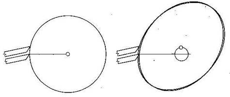
Figure 1105 Two concentric circles and two concentric ellipses twisted and penetrating each other
As a technical aid for making the central plane and central line visible J. Volmer uses a lightline projector.
 |
 |
|
|
|
|