4 Oval Chuck and Ovalturning Lathes |
 |
4.1 Review
Obviously the first not perfectly circular pieces were turned in the renaissance on lathes with the spindles controlled by cam discs both in radial and in axial directions. There are drawings in ancient books, such as in figure 3101, although the lathes in this drawing do not seem to fit with mechanical engineering laws.

Figure 3101 Lathe for Ovalturning by Salomon de Caus: Von gewaltsamen Bewegungen (About violent movements). Frankfurt 1615
Later on the principle of cam
controlled movement was applied to Rose-Engines on which, by means of
corresponding cam discs, rosettes and other complicated profiles may be turned.
This is the base for Artistic Turnery (Kunstdrechselei) and for Ornamental
Turning. The Societies of Ornamental Turning in England and in the USA are still
in action [6.4]. Occasionally oval pieces are produced using the classic oval chuck but as
rotating cutters or routers are used to shape the pieces then this is to be
considered an ovalmilling process.
In England, the Alsatian, Charles Holtzapffel designed and built turning lathes for the nobility. Such a
Holtzapffel lathe – built in 1865 - was given in 1886 by Queen Victoria to the
Archduke Otto von Habsburg as a wedding gift. It remained unchanged, with the numerous accessories complete, in Vienna . Its oval chuck is shown in
figure 3102. Holtzapffel has described its operation in the 5th volume [1.2.1]
of his great book.

Figure 3102
Oval Chuck of the Holtzapffel Lathe of Otto von Habsburg, Wien1886 [1.1.3]

Figure 3103 Heavy metal spinning lathe for oval bowls, pans and the like.(Erdmann Kircheis,Aue/Saxony)
In Germany oval chucks (Ovalwerke) of the classic type were produced until 1950. These oval chucks were screwed onto the lathe as an additional device. There were also ovalturning lathes, built as single purpose machines, on the market. The principle of the classic oval chuck was also used on machines to form shallow oval bowls and plates from porcelain clay mass and also for spinning oval pieces on spinning lathes (Figure 3103).
There are numerous patents describing improvements to the classic oval chuck. The aim of the majority of these inventions was to avoid the sliding joints and their lubrication, to compensate for the lack of balance and to achieve a smoother run. These improvements has been achieved by J.Volmer with his ovalturning lathes ODM [2.1.9]. Using the Volmer ellipse mechanism the lathe producer VICMARC/Australia [5.1] offer the VICMARC Ovalturning Device (VOD) that can be adapted to every woodturning lathe of a suitable size. Dan Bollinger/USA [6.3] built the ovalturning lathe BOTULA using a variant of the Volmer ellipse mechanism. The German woodturning craft supply SteinertÒ [5.4] presented in 2006 the small ovalturning lathe picOval. Other ovalturning lathes using the Volmer ellipse mechanism are expected in the near future.
4.2 Oval durch Querpassigdrehen
A Rose Engine (in German Querpassig-Drehbank) has a rocking headstock and an elliptical cam disc, for ovalturning, on the spindle as shown in figure 3201. The cam is held in permanent contact with a roller in the lathe frame by means of a spring.
Figure 3201
Rose engine headstock with oval cam disk
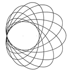
Figure 3202 Curves by an elliptical cam disk E
Few of these
lathes are in use today. They can only be operated at low speed and have been
used since the 16th century for the ivory turning. Looking at antique pieces, as
in the Ivory Collection in the Green Vault in Dresden, one can recognize the
oval forms visibly differing from the ellipse. Figure 3202 shows the curves
which the tool cuts on the workpiece, if an elliptical cam disk is used. The
curves in the middle have nodes.
;
The invention of the classic oval chuck is ascribed to Leonardo to Vinci (1452 -
1519), however there is still not absolute proof even though Leonardo has left
numerous drawings. This chuck is based on the kinematic inversion of the double
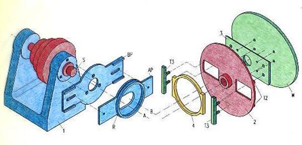
slider, the trammel. Figure 3301 shows the kinematic scheme and figure 3302 its
constructive parts. Parts with the same number in the two figures correspond.
Parts of same colour are firmly connected to each other.
Figure
3301 Kinematic scheme of the oval chuck mechanism
Figure 3302 Details
of the classic oval chuck (Explosion drawing) In the headstock 1, the driven spindle runs in
bearings. Centre plate 2 is screwed onto the spindle head S and is provided with
dove-tailed tracks T2 for slider 3, on which the workpiece W is to be mounted
either directly or by means of the faceplate or a work-holding device. Slider 3
has another pair of tracks, T3, keyed to adequate tracks on the collar plate 4
that fits over and moves around the ring R. This ring is integral with the
adjuster plate AP, and this is located between parallel bars on the backplate
BP, which in turn is fixed directly to the headstock 1. The ring plate R is
adjustable from the spindle centre A to the position B, so giving the offset
needed to make an ellipse. The distance AB is equal to the difference d of the
ellipse half-axes. Further design details are given in [2.2.6].
Figure 3303
In some German woodturner workshops and in vocational schools oval chucks of
this type can still be found, but they are rarely used. They remind one of an
once very actively applied approach to very challenging woodturning techniques.
Figure 3304 Ovalturning lathe with inertial force
balancing, adjustable while
A mechanism
analysis [2.1.2] of the classic oval chuck has shown that the unbalance
compensation problem can be solved very simply (figure 3305). We may assume that
the centre of gravity of the mass m of the elliptical workpiece, including the
work-holding devices, is located on the midpoint M of the ellipse. The point M
runs - as the ellipse motion in figure 1101 is showing – along the circle k with
the radius r = (a - b)/2. A constant centrifugal force F arises from this and
can be compensated by the diametrical centrifugal force FC of a
compensating mass mC in the distance rC from the spindle
centre M0. The relation mCrC = mr is valid. The
compensating mass mC rotates around the spindle centre M0 with double
the revolutions per minute of the workpiece.
Figure
3305 Inertial forces of the ellipse motion of the classic oval chuck
An Ovalturning
Device with unbalance compensation has been designed by J. Volmer, and in 1983
it was built in Olbernhau in the Ore Mountains (Erzgebirge). He has it tested, improved and
variously used (figure 3306) [2.1.1].
Figure
3306 Ovalturning Device (ODV) with unbalance compensation The
Volmer-Ovalturning-Lathes (ODM) generate the ellipse motion (figure 1101) by
means of a special ellipse mechanism of the following construction (figure
3401).
On the head SK of the driven spindle is screwed the main
plate SS. On this the plate PL is adjustable mounted. The offset of plate PL is
adjustably within the range of 0 to maximal 30 mm. This is the distance between
the stub axle AB and the spindle axis, and it is related to the quarter of the
axes´ difference of the ellipse to be turned. On axle AB rotates the tooth belt
wheel R4 with its hub NA. Onto NA are screwed either the faceplate PS or the
flange
of a work-holding device. Wheel R4 is driven via tooth belt ZA2 by
wheel R3 which is on one shaft together with wheel R2, and this is driven via
tooth belt ZR1 by wheel R1 that is fixed to the headstock. For two revolutions
of the main plate SS the faceplate PS turns one revolution. Tooth belt ZR1 is
tensed by eccentric disk EX1, and tooth belt ZR2 by idler pulley SR and
eccentric disk EX2. The mass GM balances the masses of the wheels R2, R3 and
pulley SR. The countermass AM is dimensioned and positioned according the position and mass
of plate PL and parts on it including the workpiece and work-holding devices.
The mass of the latter must be known. The turner can read these countermass
parameters from diagrams, any calculations are not necessary.
Figure 3402 Ovaldrehmaschine ODM15 <
Figure 3403 >>
Figure 3404
Dan Bollinger, USA, has built a complete Ovalturning Lathe with a variant of the
Volmer ellipse mechanism. Its maximum ellipse axes difference (sway) is very
large.
Figure 3405 Bollinger Ovalturning Lathe (BOTULA )
[6.3]


P Cam (Patrone), W Workpiece
4.3 The Classic Oval Chuck (Ovalwerk)

Oval chucks of this design were manufactured in different sizes by many lathe
producers in Europe. Figure 3303 shows an oval chuck made by the German company
Alexander Geiger in Ludwigshafen. It is in the possession of Mike Darlow in
Australia [1.2.9].

Oval chuck made by Alexander Geiger, Ludwigshafen, about 1930, in
possession of Mike Darlow, Australia
There were also single purpose ovalturning lathes on the market. Headstock and
oval chuck formed a single unit. As single-purpose-machines they had great
advantages in comparison to the oval chuck as an accessory. They often had solid
foundations to absorb the unbalanced forces which resulted from the ellipse
motion.
Many endeavors were dedicated to the compensation of these unbalanced forces in
order to achieve a smooth run of the lathe and to reduce their effect on the
ovalturner. There were many different inventions which dealt with this problem.
The German company Alexander Geiger found practical solutions to this problem.
In 1909 Pryibil, an American company, used a theoretically exact solution to
build an ovalturning lathe which overcame the out-of-balance problem. Their ovalturning and oval spinning lathes were equipped with a brilliant but very
complicated mechanism, even adjustable whilst the lathe was running (figure
3304). Unfortunately none of these machines has survived.

running
(Company P. Pryibil, New York 1909)


(VEB Olbernhauer Maschinenfabrik, Olbernhau Ore Mountains 1983)
4.4 Ovalturning Lathes (ODM)

Figure 3401 The ellipse mechanism of the Ovalturning
Lathe ODM30
Two prototypes have been built: The Ovalturning Lathe ODM15 (figure 3402) for a
maximum ellipse axes difference (sway) of 60mm, and the bigger ODM30 (figure
3403) for 120mm. The VICMARC Ovalturning Device (VOD) has the size of the ODM30,
in figure 3404 screwed on a WEMA-headstock [6.5].
(Werkstatt
J. Volmer, Chemnitz 1989) Foto: G. Göthl
Ovalturning
Lathe (Ovaldrehmaschine) ODM15
(Workshop J. Volmer,
Chemnitz 1993)

VICMARC Ovalturning Device (VOD)
(VICMARC Maschinery Australien 2000)
at Wema Headstock GAMMA
(WEMA Olbernhau [6.5] )
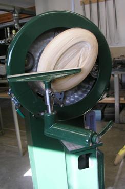

Figure 3406 Ovalturning lathe picOval (Drechselzentrum Erzgebirge Steinert®, 2006)
 |
 |
|
|
|
|