9 Ornamenting |
 |
9.1 Decorations
Oval turned objects can be decorated by painting, carving or ornamentation. Ornaments are cut into the surface using routers or rotating profiled cutters. The early Ornamental Lathes, e.g. those made by Holtzapffel in England, were equipped with the relevant mechanical devices. Many of these devices were invented by the mechanics and court turners of the European sovereigns [1.1.3].
Many of the early artifacts of former times, which are now preserved and can be seen in museums, seem to us to be overloaded with decorative elements, but they prove the extraordinary skill of the old masters and the existence of ingenious mechanisms. Even today ornamentation can increase the aesthetic value of oval turned objects. The artistically ambitious ovalturner has wide scope for design. There are no real rules to use as a guide when adding decoration. It comes down to personal taste.
Decorative details can consist of points, straight lines, circles and arcs, which are cut or routed into the surfaces of the workpieces. Figure 6101 shows a routed lidded oval box made by Foster Giesmann / USA. He was an active experimentator at his complete workshop-made ornamental lathe [2.2.4], [3.1], equipped with a Rivington indexer. Members of Society of Ornamental Turners (SOT) in England [6.4] and in the USA add to the range of wonderfully decorated oval turned (or milled) objects.

Figure 6101 Oval lidded box with equally spaced routed ornaments (Foster Giesmann / USA, 1998 [2.2.6] )
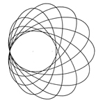
The ellipse itself can be used as ornament, for instance when using the oval chuck and a fixed or rotating knife a series of ellipses may be cut into the lid of a plain box. Examples of interesting patterns are to be found in the Holtzapffel book [1.2.1]. Figure 6102 shows examples.
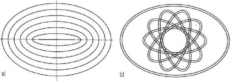
Figure 6102 Ellipses as decorative ornaments
a) Ellipses with same axes difference
b) Pairs of ellipses, twisted by 36 degrees
9.2 Division of the Ellipse
When locating ornaments lengthways around an ellipse the old problem, to achieve equal distances between the ornaments, is discovered. This problem does not appear with circular turning; dividing the circle is achieved using the division plate. If a division plate is used in conjunction with the oval chuck unequal distances between the division points result (figure 6103a). Using the Indexer, a special mechanism, equally spaced division points are obtained (figure 6103b).
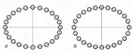
Figure 6103
Division of the ellipse in 24 parts
a) by division plate: distances
unequal
b) by Indexer: distances equal
By means of the band-method the perimeter of the ellipse can be easily divided into a required number of parts. At a single workpiece one can try to find the division points by trial and error. Calculate the perimeter and divide by the required number. This is approximately the distance for a trial using the dividers.
9.3 Bandmethod
Wind a paper tape PB around the workpiece on the ellipse to be divided in n parts and stitch with a needle the point on the vertex line h (figure 6201a). Stretch the band PB on the drawing board. The needle points are the start-point A and the end-point B. Draw the line AB, divide its length l = AB by n and take the rounded distance in the dividers. Draw this distance n- times on an arbitrary line g, beginning in A. The end point is C. Draw the line CB and parallels of CB through every point of line g, thus giving the dividing points on the tape. Rewind the tape in same position and stitch the dividing points onto the workpiece.
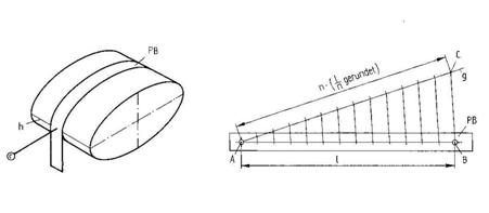
Figure
6201 Bandmethod
a) Paper band PT around the elliptical
workpiece
b) equal division of the line AB in n parts
9.4 Indexer
Indexers are mechanisms that make possible the equal division of an ellipse on an oval turned workpiece. The workpiece is held in the oval chuck or on the ovalturning lathe whilst the indexer is used to equally divide the elliptical edge or face. A motorized tool, a router or a profiled cutter, is positiond on the central line when cutting the ornament into the surface of the workpiece. Figure 6301 shows, as an example, the cutting of 30 equally spaced small circle on the face of an elliptical cylinder chucked in the classic oval chuck.
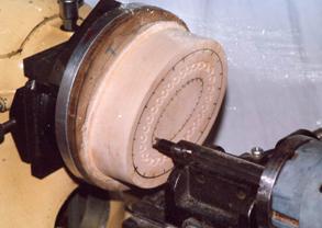
Figure 6301
Cutting of 30 circle grooves equally spaced along an
ellipse on
the face of cylinder on a classic oval chuck
(Workshop E. W. Newton, Bradford 1994)
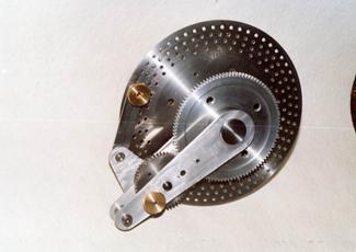
Figure 6302
Indexer ICI for the classic oval chuck
(Workshop J. Volmer 1994)
Holtzapffel [1.2.1] describes the Compensating Index as an Indexer. This ingenious but probably empirically dimensioned mechanism was invented around 1830. A kinematical analysis [1.2.5] has shown that this indexer could be substantially improved. Hence the Improved Compensating Index (ICI) has been constructed as indexer for the classic oval chuck (Figure 6302). A detailed instruction for its operation was published by the Society of Ornamental Turning [1.2.6]. For the adjustment of the ICI only the axes ratio of the ellipse to be divided is of importance, not its size..
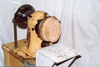
Figure
6303
Indexer ICI installed at the Myford Woodturning Lathe ML8(Workshop E. W. Newton,
Bradford 1994)

Figure 6304
Indexer for Ovalturning Lathe ODM15
(Workshop J. Volmer, Chemnitz
2000)
The Indexers for the Ovalturning Lathes ODM15 and ODM30 have a simple structure. The index pin is moved up and down by a linkage dependant upon the revolution of the workpiece. The amplitude of this rocking motion is related to the axes ratio of the ellipse to be divided. The instruction manual gives the relation between the axes ratio and the eccentricity of the driving cam to be adjusted. The Indexer alone cannot firmly hold the workpiece against the forces that arise during the ornamenting process. On the ODM30 a brake, operated by a cam, clamps the main disc of the ellipse mechanism.
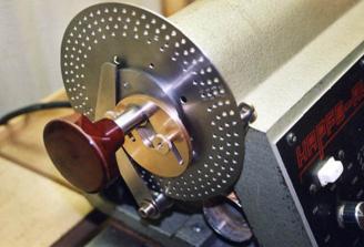
Figure 6305
Indexer for Ovalturning Lathe ODM30
(Workshop J. Volmer, Chemnitz 2001)
Figure 6306 shows as an example the lid of a box with 32 circles intersecting each other. They form the Barley-Corn-Pattern. The circles were cut by a rotating knife made of 2mm steel sheet. The motor is mounted on the coupler of a straight line linkage that moves the cutter vertically to the lid (figure 6.3.7).

Figure 6306
Lid of a chip box with 32 equally spaced circles forming the Barley-Corn-Pattern
(Workshop J. Volmer, Chemnitz 2003)
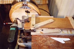
Figure 6307
Routing motor with circle cutter at a straight line linkage
(Workshop J. Volmer, Chemnitz 2003)
 |
 |
|
|
|
|