6 Methods of Ovalturning |
 |
6.1
Guiding the Tool
The essential differences between ovalturning and normal (circular) turning are the ellipse motion of the workpiece and the complicated tool guiding resulting from this motion. The cut should always be carried out in the central plane or lengthwise along the central line. When circular turning it does not matter whether the position of the cutting edge of the tool is above or below centre height as circles are always produced concentric to the spindle axis. When ovalturning the position of the cutting edge plays an essential roll.
.

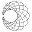
Figure 5101 Result of tool positions at the circular cylinder and at an elliptical cylindrical workpiece
Figure 5101 right shows an ellipse cut by the centrally positioned edge and an ellipse cut by an edge positioned above the central line. The two ellipses penetrate each other. This means that the ellipse cut centrally is penetrated by the ellipse cut more highly. Two facing grooves arise on the surface. If such grooves appear at the cylindrical area of the oval turned workpiece, this shows that the tool edge was not guided centrally. Only by guiding the edge centrally can one achieve a clean surface. The tool should cut, theoretically, with a point of its edge in order to obtain an exact ellipse but this is practically impossible. Therefore the ovalturner uses pointed gouges. Scrapers, as they may be held horizontally at a precise height and position, enable the turner to always cut on a central line.
6.2 Lightline

Figure 5102
Scheme of the Lightline-Projection
In order to make the central line at the workpiece visible and to guide the cutting edge exactly along this line J. Volmer uses a lightline. It is generated using a projector with a special slide or using a laser. When the workpiece is rotating, the line will remain static allowing the tool to follow this correct path. An added important benefit is that this lightline clearly shows the turned profile as work progresses. The projector generates a lightplane, and is positioned so that the lightplane coincides with the central plane. A template is used to adjust the projector on its stand. It is placed on the lathe bed in front of the workpiece and has a marked horizontal line at centre height with which the projected lightline must coincide (see figure 5504).

Figure
5103
Application of the lightline when turning the inside of an oval bowl. The projector is on a stand, about 1.5 m in front on right side, separate of the ovalturning lathe ODM30.

Figure 5104
The lightline makes the internal profile of the finished bowl visible, it is standing still in spite of the bowl´s running.

Figure 5105
The lightline shows the fine profile of a frame (here a rectangular frame) exactly visible while the workpiece is rotating. The tool has cut along the projected lightline.
6.3 Ovalturning Tools
The ovalturning tools are free hand guided gouges and scrapers and, in some cases, chisels. The gouges are ground to a lady-finger shape in order to have a short cutting area at the edge. The side parts of those edges are used for straight surfaces. The wedge angle depends on the type of wood to be cut. Scrapers have different edge profiles, e.g. straight edges for recesses and round for inside profiles of deep and shallow bowls.

Figure 5201
Ovalturning tools
For hard materials, like bone, ivory, horn and soft stones, one uses turning tools formed for non-ferrous metals. Those tools are fixed in a compound slide rest and fed into the workpiece slowly. Figure 5202 shows, as an example, ovalturning napkins rings from cattle bone.

Figure 5202
Ovalturning rings of bone at the ODM15 with the tool in the compound slide rest
When
ovalturning a series of identical workpieces special devices are helpful to
ensure uniformity. For this purpose the Piercer (Stecher) was designed following
the example of the Bankfräser, common in the Ore Mountains (Erzgebirge). The
piercer is used, for instance, to produce exactly the same diameter of the
recess in all the frames of a series. The piercer consists of a swivelling arm,
also movable in direction of the spindle axis. Upon the arm is fastened at a
certain position a narrow pointed gouge . The arm lies on the tool rest or with
an adjustable stopper on the lathe bed. The axis direction is also limited by an
adjustable stop.

Figure 5203
Piercer at the ovalturning lathe ODM15 with its arm in working position
>
Figure 5204
Marking
the recess edge at a small rectangle picture frame by the piercer. The small
pointed gouge is fastened upright and stings exactly on the center line
At the ovalturning lathes if rotating profile knives or routers are used,
instead of hand-held woodturning tools, then Parallel Curves of the ellipse are
cut. These curves are not ellipses. Woodturners who make workpieces in this way
at the oval chuck, because it is an easier method of production, are often
surprised with the results. The curves obtained by milling can visibly differ
from that of the ellipse, they can even have cusps (figures 5206 and 5207).
Figure 5206
Figure 5207
The
oval chuck or the ellipse mechanism of the ovalturning lathe guides the
router-axis C relatively to the workpiece on the ellipse e (figure 5208a). A
cylindrical router with radius r cuts the outer curve qo and the inner curve qi
into the face of the workpiece. Both curves have the distance r to the ellipse
e. They are called Equidistant or Parallel Curves. While qo is similar with the
ellipse e the inner parallel curve qi shows visible deviations of the ellipse e.
For small axes ratios qi has a cusp (figure 5208b), and for a smaller ratio
arises undercut (figure 5208c). The mathematical relation for that is r/b => b/a
(compare figure 2102). The
Parallel Curves of the ellipse have been investigated in the 19th century, e.g.
by the renown British mathematician Arthur Cayley (1821 - 1895). They are
algebraic curves of eighth order and called Toroides.
On oval bowls or plates the effects of ovalmilling mentioned above may not disturb.
Problems can appear at fits of two oval milled parts, e.g. when matching a
lid with its box. In figure 5209 the router is guided for cutting the outer contour
q1 of the box along the ellipse e1, for cutting the inner contour q2 in the lid
along the ellpise e2. Both ellipses have the same axes difference, i.e. both
contours are milled with the same adjustment of the oval chuck.
Figure 5208
Figure 5209
Oval
bowls, plates, platters, frames and many more of the oval objects mentioned in
the list of oval turned items for use in general are turned as facework, i.e.
of cross grain blanks. In ovalturning the flatter the object the more simple is
the turning process. Ovalturning of deep objects, bowls or vases for instance,
is more complicated. In the old literature there is no description of the way
tool are used to produce the cleanest cuts and smoothest surfaces. Using
scrapers, shavings can easily be made but producing a smooth surface on wooden
pieces is not so easy. Spannagel, the author of the German woodturner bible „Das
Drechslerwerk“, published in 1940 [1.1.2], wrote, in the chapter Ovalturning,
that the only way to get acquainted with the practice of ovalturning,
especially handling the tools, is to watch an efficient and competent master.
Unfortunately such a master is not be found easily today. On the other hand,
the masters hardly understood the geometric relations because any books of the
time presented, at the most, a scant outline showing that the tool has to cut
in spindle height. Scrapers have, historically, been used in preference to
gouges. It is easier to lay scrapers on a plane tool rest enabling it to be
kept at centre height.
The
first book that was dedicated exclusively to ovalturning of frames was the
German "Handbuch der Ovaldreherei" (Manual of Ovalturning)[1.1.1]. It was
written in 1920 by Hugo Knoppe, meritorious teacher at the Technical College
for Turners, Carvers and Sculptors in Leipzig / Saxony.
Oval
frames were produced in large quantities in frame-making factories. The frame
blanks were made up of 4 or 6 parts. Each factory had its own technique for
joining the frame blank parts, predominant were mortise and tenon joints as
seen preserved in the oval frame factory, The Old Schwamb Mill in the USA
[6.2]. In Germany there was a factory that offered horseshoe-like bent wood
arcs. The arcs were glued together using a scarf joint. These frame blanks had
the advantage that the fibres ran lengthways with the oval, and that assisted
in yielding a good surface finish.
The
frame factories delivered frames of all sizes, all profiles and ornaments and
all manners of surfaces, e.g. painted, gilded, with spun metal inlays and also
natural. The skills shown in the production of these forms were excellent.
Today those same skills are less easily found. However, the oval frame form
still compliments many a picture format. The ovalturning of picture and mirror
frames is still of current interest and provides a special challenge.
The
simplest form and therefore the simplest task is the production of a
rectangular frame with an oval profile and an oval recess [2.2.11]. Up to a
certain size – about 14 by 19 centimetre - the rectangle can be made from a
solid board. Hard woods are preferred. In order to avoid warping, the grain of
the frame blank boards should run as shown in figure 5401a, but not as in
figure 5401b. Larger rectangles should be made up of 4 parts (figure 5402).
Figure 5401
Figure 5403 Half-axes of the picture-ellipse
The
picture-ellipse should have an axis ratio matching with the picture, e.g. for
portraits b/a not smaller than 0,75 (figure 5403).
Figure 5404
Figure 5405
Figure 5407
Figure 5409
It is
preferably to turn the profile P within the rectangular border S (picture 5410a
and b), because a protruding profile (figure 5410c) requires to turn over the
rest of the rectangle area S. This is difficult to turn cleanly because of the
interrupted cut. The picture B can be put into the frame from the front side
(figure 5410a) or into a recess in the rear (figure 5410b and c). The picture B,
an inlay or a passepartout and the glass G are held by a rattan clamp-ring C
(figure 5411). On the rear recess two curved wires CW keep the cover CR down
[2.2.11]. Glass, passepartout, inlays and cover are cut by means of an
ellipsograph provided with a cutting wheel or knife Figure 5410 Frame cross sections
Figure 5411
Figure 5413
Figure 5414 Example: Big
rustic bowl of wet cherry.
Figure 5501
Figure 5502
Turn outer contour of the bowl using pointed 16mm gouge, on the base turn a
10mm deep spigot.
Figure 5503
Screw a hardwood board to the faceplate, turn a recess to match the spigot,
press the bowl spigot into the recess, do not hammer, apply pressure only to
the middle of the bowl (5.7kg).
Hollow
using a bowl gouge, smooth with rounded scraper. Wrap
the
bowl in newspaper or place it in a cloth bag, with shavings, to dry. Wind a
steel band around to prevent cracking of the end grain. At intervals tighten the
band using the screw lock. Once it is dry remove the spigot, sand the bowl
roughly and oil it (1,6kg).
Workpieces are described as long grain work when the grain runs in direction
of the spindle ax*is. At circular turning long grain pieces – e.g. banisters –
are turned between pins. At ovalturning this method is impossible due to the
ellipse motion. The workpiece cannot be supported by the tailstock pin. Short
long grain pieces can be chucked in a chuck with normal or extended jaws.
Figure 5601 shows a box as example.
Figure
5601
Figure 5602
The
following figures show as examples of the application of the ELLPIN device the
ovalturning of cutlery handles and of bashers or mallets. The blanks have to be
prepared: they are turned round between pins and of wanted lengths, holes at the
ends have to be drilled for the ball-pin and for the screw or a cone is to be
turned matching with the ELLPIN cup chuck. Figure 5603
Knife
and fork with tang and ferule,
Sawed
ebony blanks
Figure
5605
After
centre punching both ends the hole for the ball-pin is drilled
Figure
5606
Turning the conical spigot at the handle end using a template, white mark on the
broad side
Check the fit of the spigot in the conical hole in the ELLPIN-flange
Figure 5608
Press
spigot into the hole of ELLPIN-flange, and press ball-pin into the blank. Notice
the position of the white mark
Adjust the ellipse mechanism to provide the correct size of the ellipse at the
handle end, cut along the lightened central line, the round part at the end of
the handle must fit the ferule..
Sanding and polishing near the central line
Figure 5611
Figure 5612
Pull
out the ball-pin using the extractor (workshop J. Volmer) and enlarge the hole
to fit the tang, saw off the spigot and sand the elliptical end round.
Figure 5613
Basher for kitchen work as meat basher or as mallet for wood
sculptors
At
the start the basher blanks are turned round between centres to the required
length. The ends are slightly rounded over. The hole for the ball-pin at the
handle end and the hole for the ELLPIN-screw-chuck at the other end are to be
drilled coaxially. The blank is now screwed onto the ELLPIN-screw-chuck, and the
prong ring – there are two diameters 20mm and 32mm – as anti-twist device must
be pressed firmly into the face by revolving the wooden disc. The ball-pin is
pressed into the handle end and the ball inserted in the ball pan at the
tailstock.
The
possibilities of the design of shapes and profiles of objects turned using the
ELLPIN device are endless. Some experimental candle-holders have been produced.
Figure 5615

 Figure
5205
Figure
5205
After
roughly turning the recess using hand-held tools, to within one or two
millimetres of the required size. Using the piercer the recess wall is now
neatly cut 6.4
Ovalmilling

Routing-Motor with chucked
Two-Knife-Ball-Cutter, fixed in a compound slide rest, milling the underside of
a bowl at the Bollinger Ovalturning Lathe (BOTULA) [6.3]

Milling the bowl underside [6.3]
Parallel curves qi und qo of ellipse e with different axes ratios b/a and
router-radius-ratio r/b
a) b/a = 0,67 r/b = 0,38
b) b/a = 0,50 r/b = 0,50 (cusp at qi)
c) b/a = 0,33 r/b = 0,75 (undercut)
Ovalmilling of outer and inner contour with same adjustment of the oval chuck
6.5 Ovalturning of Facework (Cross Grain)
6.6 Ovalturning of Frames

Oval frame of a rectangle board
a) Quarter-sawn b) Plain-sawn


Figure 5402
Rectangle frame blanks 
Frame rectangle in the two-jaw chuck at the ODM15
Rectangular workpieces are chucked in the two-jaw chuck as seen in figure 5405
fixed on the ODM15 (with adjusted lightline). The two ellipses, between which
the profile is to be cut, are drawn onto the running workpiece using a fixed
marker set exactly at centre height (figure 5405).
Drawing the ellipses bordering the profile

Marking the picture-ellipse by the piercer
It
always pays to make a series of the same pieces, and it is profitable to use the
piercer to produce recesses exactly equal in size for all frames of the series
(figure 5406). The recess and the profile are cut using narrow pointed gouges.
The bottom is flattened using a straight edged scraper. Take care to leave
sufficient thickness TH at the back of the frame. The profile is sanded to a
fine finish using folded sandpaper (figure 5408), the front is cleaned up using
a sanding block. The distances of the profile from the opposing rectangle sides
should be equal (figure 5409).
Turning the profile and the recess
 Figure 5408 Sanding
the profile near the central line
Figure 5408 Sanding
the profile near the central line
Finished frame, bottom flattened by scraper

S frame area, R picture area, W recess edge, P profile area, B picture ,
Glass, CR cover, C rattan clamp-ring,
CW curved wires,
T profile tangent, if possible vertical to S,
TH
thickness of bottom
a) front recess b) rear recess c) rear recess,
protruding profile
Glass or acetate sheet, inlay and rattan clamp-ring,
on the right fitted in place


Holes on the rear for hanging the frame on small nails vertical or
crossways
The
methods described above are also used when making larger oval frames, but at the
start the blank is chucked in the claw chuck for turning the rear and the recess
W, the flank FL of the picture ellipse and the chamfer F of the outer contour
(figure 5414 above). The workpiece is then turned over and chucked on prepared
hardwood jaws of the four-jaw chuck. The last steps are turning and sanding the
profile and outer contour (figure 5414 below).
Sequence of work with big frames
W rim of picture recess, FL flank of picture ellipse,
F part of rear contour, SS space for jigsaw
6.7 Ovalturning of bowls

Saw
oval (elliptical) blank on the band
saw using a template, mass 7kg, screw the blank with hexagon headed woodscrews
from the rear of the faceplate, place between the work and the faceplate a
protective cardboard disc.


Figure 5505 
6.8 Ovalturning of Long Grain Work

Box of long grain bog oak in VICMARC Four-Jaw-Chuck on the ODM30
ELLPIN:Device for ovalturning long
workpieces (Workshop J. Volmer,
type for ovalturning
lathe ODM30)
6.9 Cutlery Handles

Plastic handles are to be replaced with ebony handles


Figure 5609
 Figure
5610
Figure
5610

Finished handle


Assembling
the cutlery: press ferules onto the handles and cement the tangs
6.10
Basher and Mallet

Ovalturning Lathe ODM30 with ELLPIN (Device for ovalturning long grain work)
and chucked basher blank, right on the shelf finished bashers: Handle nearly
round, basher part with oval cross section, left the extractor for the ball-pin

Experiments using ELLPIN at the Ovalturning Device ODV
with wide cross and long grain pieces
(Workshop J. Volmer 1986)


![]()
![]()